
How to Test an Alternator with Multimeter

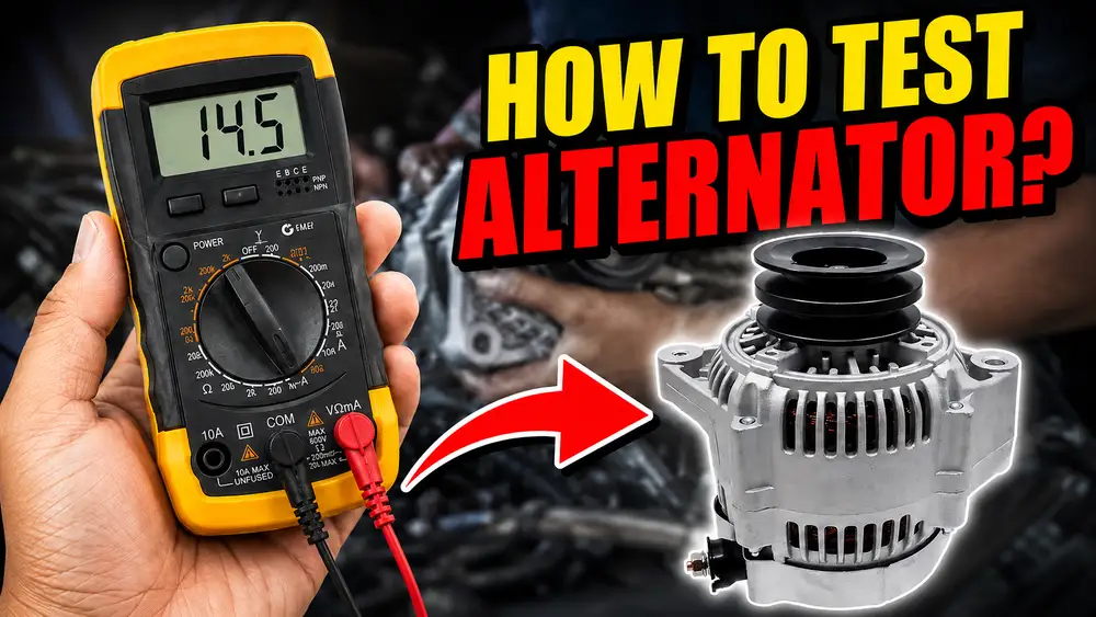
A tractor starts normally in the morning, but the battery warning light appears when the work lights come on. The next start is slow. The alternator may be weak, but the same symptoms can come from a discharged battery, loose belt, damaged cable, or poor ground.
This guide explains how to test an alternator with a multimeter on tractors, excavators, loaders, dozers, generators, and other heavy equipment. It keeps the test to three main steps: static battery voltage, charging voltage, and voltage under electrical load. Two short follow-up tests cover cable loss and AC ripple when the basic readings do not agree.
Important: The tables below are field-screening references for conventional 12V and 24V lead-acid systems. Battery type, temperature, remote sensing, regulator design, and engine speed can change the result. Use the machine or alternator service manual when its limit differs.
Safety Warning: Keep the Battery Connected
Never remove a battery cable while the engine runs to test the alternator. The battery stabilizes system voltage. Opening that connection can create a voltage transient that damages the regulator, engine controller, display, communication network, or other electrical parts.
Use a multimeter with sound, insulated leads. Secure clip leads before starting when possible, and keep hands, clothing, and test wires away from belts, pulleys, fans, and hot exhaust parts. Follow the machine’s parking, lockout, and service-door support procedures.

Pre-Test Checks
Do not use the multimeter until the belt, batteries, and main connections pass a visual check. These faults can change the reading enough to make a good alternator look bad. Correct them first, then repeat the test.
- Alternator belt: Confirm correct tension and look for cracks, glazing, oil, or missing ribs. Inspect the tensioner and pulley if the belt slips or runs out of line.
- Battery terminals: Clean and tighten both ends of the main cables. Repair heat-damaged posts, clamps, boots, or lugs.
- Cables and grounds: Look for green corrosion, broken strands, rubbed insulation, loose engine grounds, and damage at the disconnect switch or starter junction.
- Battery condition: Stop if a case is swollen, leaking, cracked, or frozen. Do not test or charge a damaged battery.
- Charge warning circuit: Check that the warning lamp behaves as the machine manual describes with the key on and engine stopped. A failed fuse, lamp, excitation feed, connector, or controller circuit can prevent charging.
- System voltage: Confirm 12V or 24V from the machine label, alternator label, and battery wiring before judging any reading.
Two 12V batteries in series form a 24V bank. Two 12V batteries in parallel still form a 12V bank, but they provide more capacity. Follow the cables instead of counting batteries.
Three Ways Test an Alternator with a Multimeter
Set the multimeter to DC volts. On an auto-ranging meter, select V⎓. On a manual-ranging meter, choose a range above the expected system voltage, such as 20V for a 12V system or a range above 30V for a 24V system.
Record the engine speed, battery temperature, electrical loads, battery-bank voltage, and alternator B+ voltage. A number without its test conditions cannot support a repair decision.
Step 1: Check Static Battery Voltage
Turn off the engine and all electrical loads. For an accurate flooded lead-acid state-of-charge reading, Trojan Battery specifies at least six hours without charging or discharging, with 24 hours preferred. A 30-minute rest can provide a quick screen, but it is not as accurate.
Place the red probe on the full bank positive terminal and the black probe on the full bank negative terminal. On a 24V series bank, also measure each 12V battery. A large difference between the two batteries calls for individual battery testing before the alternator test.
| Approximate State of Charge | 12V Flooded Lead-Acid Bank | 24V Flooded Lead-Acid Bank | Action Before Alternator Test |
|---|---|---|---|
| 100% | 12.73 V | 25.46 V | Ready for testing |
| 80% | 12.50 V | 25.00 V | Usable for a quick screen; charge first for a stronger test |
| 60% | 12.27 V | 24.48 V | Charge before judging alternator output |
| 50% | 12.10 V | 24.20 V | Charge and test each battery |
| 40% | 11.89 V | 23.92 V | Battery bank is discharged; do not condemn the alternator |
These values come from Trojan Battery’s flooded lead-acid open-circuit table at 25°C (77°F). AGM, gel, lithium, recently charged, and cold batteries need their own data. Static voltage shows state of charge, not battery capacity or cranking health.
Step 2: Measure Charging Voltage
Attach the meter across the full battery bank, then start the engine. Let the voltage stabilize at the engine speed stated in the service procedure. If no procedure is available, record idle and a steady fast-idle reading rather than using one idle number.
Measure at the battery bank first. When the reading is low, measure directly between alternator B+ and the alternator case or specified ground point. Keep the probe and lead clear of the pulley and belt.
Delco Remy’s heavy-duty procedure uses 13.8V as the lower 12V charging screen after the batteries and wiring have passed earlier checks. Its diagnostic manual states that output must not exceed 15.5V on a 12V system or 31V on a 24V system. The middle range is not a universal pass mark; temperature-compensated and controller-managed systems may command a different voltage.
Step 3: Repeat the Voltage Test Under Load
Keep the meter connected and switch on safe electrical loads. Use work lights, the cab blower, beacon, and other approved electrical circuits. Do not move the machine or operate hydraulics only to create a load.
Hold the engine at the specified test speed and record battery-bank voltage again. Then compare it with alternator B+ under the same speed and load. This screen shows whether voltage holds, but it does not measure full alternator amperage.
| Charging or Loaded Pattern | 12V System | 24V System | What to Do |
|---|---|---|---|
| Stabilized common charging screen | 13.8–14.7 V | 27.6–29.4 V | Confirm the exact machine specification, then continue the loaded test |
| Low at alternator B+ | 12.6–13.7 V | 25.2–27.4 V | Check belt speed, excitation, regulator control, and alternator output |
| High for many systems | 14.8–15.4 V | 29.6–30.8 V | Check battery temperature, remote sense, regulator, and the OEM limit |
| Delco Remy upper limit exceeded | 15.5 V or higher | 31.0 V or higher | Stop the test and diagnose overcharging |
| Battery and B+ stay inside the OEM range under load | Use the machine limit | Use the machine limit | Alternator passes the voltage-under-load screen |
| Both readings fall below the common screen under load | Below 13.8 V | Below 27.6 V | Check belt slip, battery demand, control circuits, and output current |
| B+ stays in range but the battery bank reads lower | Compare the two points | Compare the two points | Test positive and negative cable voltage drop |
| Voltage approaches rested battery level and keeps falling | About 12.7 V or lower | About 25.5 V or lower | The battery is carrying the load; charging is absent or insufficient |
A standard multimeter cannot safely measure full alternator current through its amp jack. Never place it in series with the B+ cable. Delco Remy’s professional heavy-duty output test uses a clamp meter and controlled load; more than 70% of rated alternator output counts as acceptable in that procedure.

Check Cable Voltage Drop When the Readings Differ
Long cables, battery disconnect switches, starter junctions, and frame grounds make voltage loss common on heavy equipment. Check the cable path when alternator B+ is normal but battery-bank voltage is low. Perform the test with the circuit loaded; resistance may hide when little current flows.
For the positive path, place the red probe on alternator B+ and the black probe on battery-bank positive. For the ground path, place one probe on the alternator case or ground stud and the other on battery-bank negative. Add the absolute positive and negative readings.
The voltage-drop limits appear with the ripple limits in the advanced-check table below. They apply to Delco Remy’s carbon-pile test at rated alternator output. A test made only with the machine’s lights and blower may use less current, so it cannot prove the rated-load limit, but it can still reveal where most of the loss occurs.
Check AC Ripple from the Rectifier
The alternator creates AC, and its rectifier diodes convert that output to DC. A failed diode or stator fault can leave too much AC ripple in the charging circuit. Possible symptoms include flickering lights, battery heating, unstable displays, and electrical fault codes.
With the engine running and an approved load switched on, set the multimeter to AC volts on its lowest suitable range. Fluke specifies measuring between the alternator BAT or B+ terminal and a good ground for the clearest result. The battery can smooth some ripple, so a reading taken only at the battery is a safer screen but may be lower.
| Advanced Multimeter Check | Reference Limit | Meaning and Action |
|---|---|---|
| Total charging-circuit voltage drop at rated load, 12V system | 0.50 V maximum | At or below the Delco Remy limit; continue the alternator test |
| Total charging-circuit voltage drop at rated load, 24V system | 1.00 V maximum | At or below the Delco Remy limit; continue the alternator test |
| Total voltage drop above the applicable limit | More than 0.50 V at 12V or 1.00 V at 24V | Repair cables, lugs, grounds, junctions, or the disconnect switch |
| AC ripple | 0–0.05 V AC | Desirable screen; compare with the alternator specification |
| AC ripple | More than 0.05–0.10 V AC | Repeat at the specified speed and load; verify meter contact and grounds |
| AC ripple | More than 0.10–0.29 V AC | Confirm with the OEM procedure or an oscilloscope |
| AC ripple | 0.30–0.50 V AC | Fluke fault range for likely diode or stator trouble; confirm on a test bench |
| AC ripple | More than 0.50 V AC | Exceeds the Fluke 88V manual limit; internal service or replacement is likely after confirmation |
Do not double the ripple limits simply because the machine uses 24V. Ripple is an AC component riding on the DC output, and the correct limit depends on alternator design and test method. Use the alternator manual when it gives a different value.
Read the Test Results Together
Do not replace the alternator because one value is low. Read static voltage, charging voltage, loaded voltage, cable loss, and ripple as one record. Repeat any result that changes when a probe moves.
| Combined Result | Most Likely Direction | What to Do Next |
|---|---|---|
| Static voltage is low, but charging voltage is normal | Discharged, weak, or imbalanced battery bank | Charge and test each battery; check key-off current draw if it dies while parked |
| Static voltage is ready, but battery and B+ stay low while running | Belt, excitation, regulator, controller command, or internal alternator fault | Check drive speed and control circuits, then perform an output test |
| B+ voltage is normal, but battery-bank voltage is low | Resistance in the charging cable or ground path | Use the loaded voltage-drop test and repair the high-loss section |
| Charging voltage is above the machine limit | Regulator, remote-sense circuit, ground, or battery fault | Stop and diagnose overcharging before running the machine |
| Voltage passes with light load but fails under load | Belt slip, high battery demand, cable loss, or weak alternator output | Test current with a DC clamp meter and controlled load |
| AC ripple is above the allowed limit | Rectifier diode, stator, or connection fault | Confirm with an oscilloscope or alternator bench test |
| All charging tests pass, but cranking remains slow | Battery capacity, starter circuit, or engine problem | Continue with battery and starter voltage-drop testing |
If the output test confirms an internal fault, compare repair time with replacement time. The alternator rebuild guide explains how bearings, brushes, slip rings, regulator, rectifier, rotor, and stator condition affect that choice.
Final Takeaway
A warning light starts the test, but the numbers finish it. Begin with a charged battery bank and sound belt, run the three voltage checks under recorded conditions, then use cable-drop and ripple data only when the basic readings point there.
When the measurements prove an internal alternator fault, review 12V and 24V alternators for heavy equipment by part number, rated output, pulley, mounts, and terminals. If the tag is incomplete, send Amoparts the machine details, photos, and full test record so the replacement can be checked against the evidence instead of the warning lamp alone.


